公司网站设立与维护方案竞价托管服务多少钱
SysTick 定时器
SysTick 是一个 24 位的倒计数定时器,当计到 0 时,将从 RELOAD 寄存器中自动重装载定时初值。只要不把它在 SysTick 控制及状态寄存器中的使能位清除, 就永不停息。 该定时器的介绍在MCU的手册中一般不会介绍,因为这是内核中的定时器,可查找相关内核手册来获取相关信息。该定时器一般用作于延时函数,对于一般的延时还是很方便的。
TIMER定时器
TIME定时器属于MCU的外设定时器,使用频繁且作用很大。在笔者之前的项目中TIMER定时器一般就用于计时,或者添加一个定时器的中断,用于在一定的时间后进入中断去执行相应的指令,这只是TIMER的基础用法。但是基于定时器的计数原理,可拓展的功能太多,这里就整理一下最近使用的定时器的深度用法,可大大提升定时器的应用场景。
从最常用的PWM说起。
定时器的PWM输出应该算是比较常用的功能,在LED的调光和电机控制中较为常用,下面介绍一下最基础的输出固定频率和占空比的PWM代码:
void timer_config(void)
{/* 使能 GPIOA 时钟 */rcu_periph_clock_enable(RCU_GPIOA);/* 使能 GPIOAB 时钟 */rcu_periph_clock_enable(RCU_GPIOB);/*初始化PWM输出引脚 PB0(TIMER2 CH2) */gpio_mode_set(GPIOB, GPIO_MODE_AF, GPIO_PUPD_NONE, GPIO_PIN_0);gpio_output_options_set(GPIOB, GPIO_OTYPE_PP, GPIO_OSPEED_50MHZ,GPIO_PIN_0);gpio_af_set(GPIOB, GPIO_AF_1, GPIO_PIN_0);/*初始化PWM输出引脚 PA7(TIMER2 CH1) */gpio_mode_set(GPIOA, GPIO_MODE_AF, GPIO_PUPD_NONE, GPIO_PIN_7);gpio_output_options_set(GPIOA, GPIO_OTYPE_PP, GPIO_OSPEED_50MHZ,GPIO_PIN_7);gpio_af_set(GPIOA, GPIO_AF_1, GPIO_PIN_7);/*初始化PWM输出引脚 PA6(TIMER2 CH0) */gpio_mode_set(GPIOA, GPIO_MODE_AF, GPIO_PUPD_NONE, GPIO_PIN_6);gpio_output_options_set(GPIOA, GPIO_OTYPE_PP, GPIO_OSPEED_50MHZ,GPIO_PIN_6);gpio_af_set(GPIOA, GPIO_AF_1, GPIO_PIN_6);/* 结构体 */timer_oc_parameter_struct timer_ocinitpara;timer_parameter_struct timer_initpara;/* 使能定时器时钟 */rcu_periph_clock_enable(RCU_TIMER2);timer_deinit(TIMER2);/* 初始化TIMER相关结构体参数 */timer_struct_para_init(&timer_initpara);/* TIMER2 初始化 */timer_initpara.prescaler         = 71;                //预分频值timer_initpara.alignedmode       = TIMER_COUNTER_EDGE;//对其模式timer_initpara.counterdirection  = TIMER_COUNTER_UP;  //计数方向timer_initpara.period            = 15999;             //周期timer_initpara.clockdivision     = TIMER_CKDIV_DIV1;  //时钟分频因子timer_initpara.repetitioncounter = 0;                 //重复计数值timer_init(TIMER2, &timer_initpara);/* 初始化定时器通道输出参数结构 */timer_channel_output_struct_para_init(&timer_ocinitpara);/* 配置定时器通道输出功能 */timer_ocinitpara.outputstate  = TIMER_CCX_ENABLE;                   //通道输出状态timer_ocinitpara.outputnstate = TIMER_CCXN_DISABLE;                 //互补通道输出状态timer_ocinitpara.ocpolarity   = TIMER_OC_POLARITY_HIGH;             //通道输出极性timer_ocinitpara.ocnpolarity  = TIMER_OCN_POLARITY_HIGH;                        //互补通道输出极性timer_ocinitpara.ocidlestate  = TIMER_OC_IDLE_STATE_LOW;                        //空闲状态下通道输出timer_ocinitpara.ocnidlestate = TIMER_OCN_IDLE_STATE_LOW;           //空闲状态先互补通道输出极性timer_channel_output_config(TIMER2, TIMER_CH_0, &timer_ocinitpara);timer_channel_output_config(TIMER2, TIMER_CH_1, &timer_ocinitpara);timer_channel_output_config(TIMER2, TIMER_CH_2, &timer_ocinitpara);/* CH0 configuration in PWM mode0, duty cycle 25% */timer_channel_output_pulse_value_config(TIMER2, TIMER_CH_0, 4000);//设置通道比较值timer_channel_output_mode_config(TIMER2, TIMER_CH_0, TIMER_OC_MODE_PWM0);//设置通道输出比较模式timer_channel_output_shadow_config(TIMER2, TIMER_CH_0, TIMER_OC_SHADOW_DISABLE);//配置TIMER通道输出比较影子寄存器功能/* CH1 configuration in PWM mode0, duty cycle 50% */timer_channel_output_pulse_value_config(TIMER2, TIMER_CH_1, 8000);timer_channel_output_mode_config(TIMER2, TIMER_CH_1, TIMER_OC_MODE_PWM0);timer_channel_output_shadow_config(TIMER2, TIMER_CH_1, TIMER_OC_SHADOW_DISABLE);/* CH2 configuration in PWM mode0, duty cycle 75% */timer_channel_output_pulse_value_config(TIMER2, TIMER_CH_2, 12000);timer_channel_output_mode_config(TIMER2, TIMER_CH_2, TIMER_OC_MODE_PWM0);timer_channel_output_shadow_config(TIMER2, TIMER_CH_2, TIMER_OC_SHADOW_DISABLE);timer_auto_reload_shadow_enable(TIMER2);//自动重载影子使能/* TIMER2 使能 */timer_enable(TIMER2);}
首先要明白定时器的输出的引脚并不是随便定义的,具体可参照手册来确定:
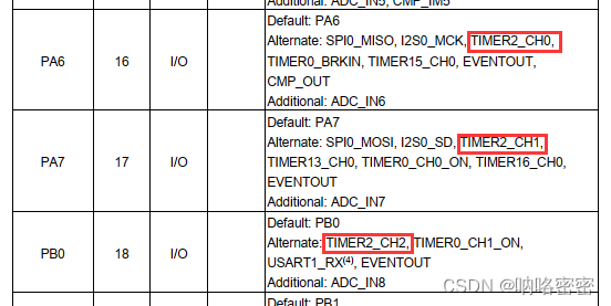
其次在使用PWM功能时我们主要关注的是输出波形的频率和占空比,那么这里我们对定时器的设置主要就是设置预分频值(prescaler)和周期(period)以及通道比较值。在上述例程中我使用TIMER2,预分频值为72-1=71,周期为16000-1=15999。系统时钟72M,那么得以计算出:
定时器的时钟频率为TIMER2CLK=systemcoreclock/prescaler = 72MHz/72=1MHz
PWM的频率为TIMER2CLK/period=1MHz/16000 = 62.5Hz.
TIMER2 通道0占空比 = (4000/ 16000) 100 = 25%
TIMER2 通道0占空比 = (8000/ 16000) 100 = 50%
TIMER2 通道0占空比 = (12000/ 16000)* 100 = 75%**
如果我们需要动态调节频率和占空比只需调用以下函数:
设置预分频值:
timer_prescaler_config(uint32_t timer_periph, uint16_t prescaler, uint8_t pscreload)
timer_periph:TIMERx(x=0,2,5,13…16)
prescaler:预分频值。
pscreload:生效时间。(TIMER_PSC_RELOAD_NOW:立即生效 TIMER_PSC_RELOAD_UPDATE:下次更新事件到来生效 )
设置通道输出脉冲值(占空比)
timer_channel_output_pulse_value_config(uint32_t timer_periph, uint16_t channel, uint32_t pulse)
timer_periph:TIMERx(x=0,2,5,13…16)
channel:通道值
pulse:通道输出脉冲值
至此,一个简单的PWM输出便完成了,但是当我们想平滑的控制一个灯的亮灭,总不能一直通过函数来进行不停地改变占空比,于是这里可以启用TIMER的DMA功能。
定义TIMER0通道1的地址:#define TIMER2_CH0CV ((uint32_t)0x40000434)
定义一个需要的数组变量:uint16_t buffer[3] = {4000, 8000, 12000};
添加DMA初始化:
void timer_dma_config(void)
{dma_parameter_struct dma_init_struct;/* enable DMA clock */rcu_periph_clock_enable(RCU_DMA);/* initialize DMA channel4 */dma_deinit(DMA_CH2);/* DMA channel4 initialize */dma_init_struct.periph_addr  = (uint32_t)TIMER2_CH0CV;dma_init_struct.periph_inc   = DMA_PERIPH_INCREASE_DISABLE;dma_init_struct.memory_addr  = (uint32_t)buffer;dma_init_struct.memory_inc   = DMA_MEMORY_INCREASE_ENABLE;dma_init_struct.periph_width = DMA_PERIPHERAL_WIDTH_16BIT;dma_init_struct.memory_width = DMA_MEMORY_WIDTH_16BIT;dma_init_struct.direction    = DMA_MEMORY_TO_PERIPHERAL;dma_init_struct.number       = 3;dma_init_struct.priority     = DMA_PRIORITY_ULTRA_HIGH;dma_init( DMA_CH2, &dma_init_struct);/* enable DMA circulation mode */dma_circulation_enable(DMA_CH2);/* enable DMA channel4 */dma_channel_enable(DMA_CH2);
}
将之前的通道0的输出脉冲值修改成buffer数组:
timer_channel_output_pulse_value_config(TIMER2, TIMER_CH_0, buffer[0]);
TIMER0更新DMA请求启用
timer_dma_enable(TIMER2, TIMER_DMA_UPD);
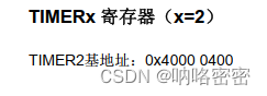
TIMER2_CH0CV为定时器2通道0的地址,该地址可通过手册查询:
先找到TIMER2的基地址:
再找到通道0的偏移地址:
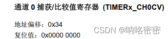
两个地址相加得到TIMER2_CH0CV。
buffer数组为需要设置的脉冲宽度,根据需要扩充大小,数据越多,波形变化越平滑,这里为了试验只取了三个数组。
对于DMA通道的选择可以注意一下:
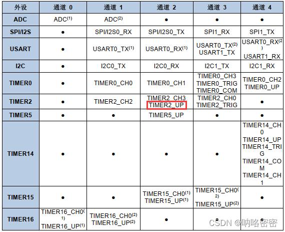
选择的是TIMER2_UP,而不是TIMER_CH0!!!
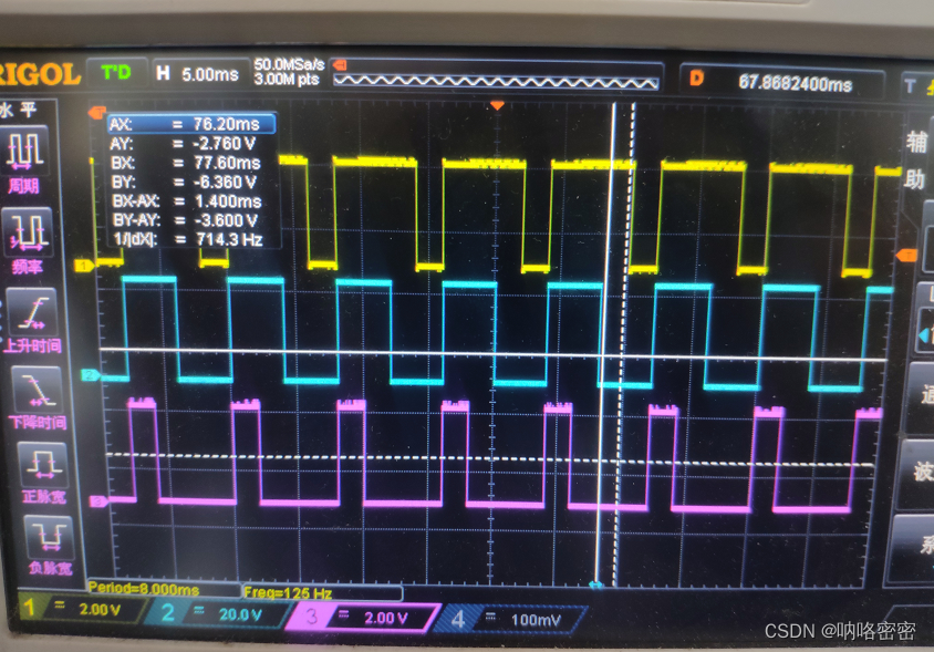
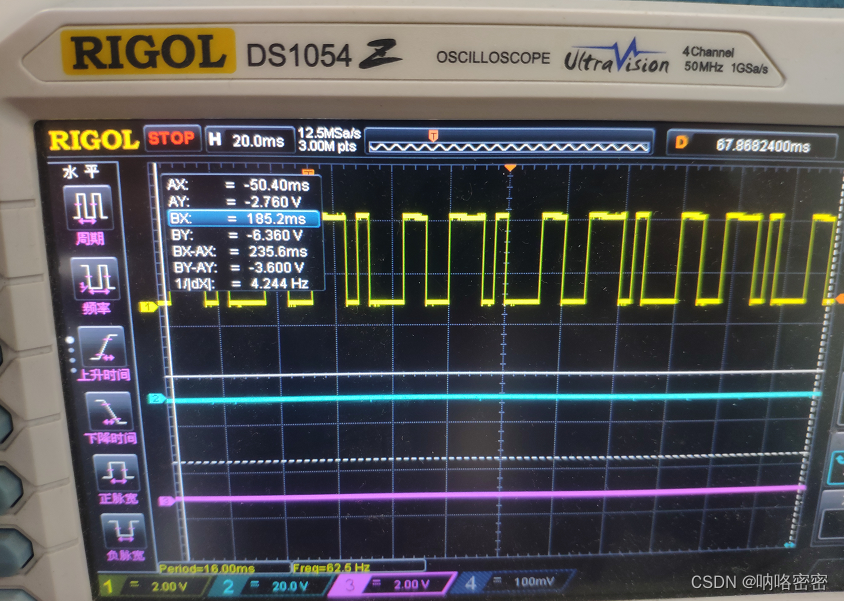
示波器采样如下:
主从定时器(定时器互联)
在使用定时器的过程中,有时一个定时器并不能满足我们的需求,此时可以尝试使用定时器的级联,将某个定时器作为主定时器,另一个作为从定时器,从而达到自己的目的。
三个相互级联的PWM输出:
需求:一路固定以250HZ的频率输出PWM,二路以62.5Hz频率输出,三路以15.625Hz频率输出。
可以看出来他们之间使4倍的关系,可以以一路为主定时器,二路为从定时器,捕获一路4个更新事件输出一个周期信号,同时二路作为三路的主定时器,三路捕获二路四个更新事件输出一个周期信号。
代码实现:
void timer_config(void)
{rcu_periph_clock_enable(RCU_GPIOA);/*PA2(TIMER14 CH0)*/gpio_mode_set(GPIOA, GPIO_MODE_AF, GPIO_PUPD_NONE, GPIO_PIN_2);gpio_output_options_set(GPIOA, GPIO_OTYPE_PP, GPIO_OSPEED_50MHZ,GPIO_PIN_2);gpio_af_set(GPIOA, GPIO_AF_0, GPIO_PIN_2);/*PA6(TIMER2 CH0)*/gpio_mode_set(GPIOA, GPIO_MODE_AF, GPIO_PUPD_NONE, GPIO_PIN_6);gpio_output_options_set(GPIOA, GPIO_OTYPE_PP, GPIO_OSPEED_50MHZ,GPIO_PIN_6);gpio_af_set(GPIOA, GPIO_AF_1, GPIO_PIN_6);/*PA8(TIMER0 CH0)*/gpio_mode_set(GPIOA, GPIO_MODE_AF, GPIO_PUPD_NONE, GPIO_PIN_8);gpio_output_options_set(GPIOA, GPIO_OTYPE_PP, GPIO_OSPEED_50MHZ,GPIO_PIN_8);gpio_af_set(GPIOA, GPIO_AF_2, GPIO_PIN_8);timer_oc_parameter_struct timer_ocinitpara;timer_parameter_struct timer_initpara;rcu_periph_clock_enable(RCU_TIMER0);rcu_periph_clock_enable(RCU_TIMER14);rcu_periph_clock_enable(RCU_TIMER2);timer_deinit(TIMER14);timer_struct_para_init(&timer_initpara);timer_initpara.prescaler         = 71;timer_initpara.alignedmode       = TIMER_COUNTER_EDGE;timer_initpara.counterdirection  = TIMER_COUNTER_UP;timer_initpara.period            = 3999;timer_initpara.clockdivision     = TIMER_CKDIV_DIV1;timer_initpara.repetitioncounter = 0;timer_init(TIMER14, &timer_initpara);timer_channel_output_struct_para_init(&timer_ocinitpara);timer_ocinitpara.outputstate  = TIMER_CCX_ENABLE;timer_ocinitpara.outputnstate = TIMER_CCXN_DISABLE;timer_ocinitpara.ocpolarity   = TIMER_OC_POLARITY_HIGH;timer_ocinitpara.ocnpolarity  = TIMER_OCN_POLARITY_HIGH;timer_ocinitpara.ocidlestate  = TIMER_OC_IDLE_STATE_LOW;timer_ocinitpara.ocnidlestate = TIMER_OCN_IDLE_STATE_LOW;timer_channel_output_config(TIMER14, TIMER_CH_0, &timer_ocinitpara);timer_channel_output_pulse_value_config(TIMER14, TIMER_CH_0, 2000);timer_channel_output_mode_config(TIMER14, TIMER_CH_0, TIMER_OC_MODE_PWM0);timer_channel_output_shadow_config(TIMER14, TIMER_CH_0, TIMER_OC_SHADOW_DISABLE);timer_auto_reload_shadow_enable(TIMER14);/* 选择主从模式 */timer_master_slave_mode_config(TIMER14, TIMER_MASTER_SLAVE_MODE_ENABLE);/* 触发器输出使用TIMER14更新事件 */timer_master_output_trigger_source_select(TIMER14, TIMER_TRI_OUT_SRC_UPDATE);timer_primary_output_config(TIMER14, ENABLE);timer_deinit(TIMER2);timer_struct_para_init(&timer_initpara);timer_initpara.prescaler         = 0;timer_initpara.alignedmode       = TIMER_COUNTER_EDGE;timer_initpara.counterdirection  = TIMER_COUNTER_UP;timer_initpara.period            = 3;timer_initpara.clockdivision     = TIMER_CKDIV_DIV1;timer_initpara.repetitioncounter = 0;timer_init(TIMER2, &timer_initpara);timer_channel_output_struct_para_init(&timer_ocinitpara);timer_ocinitpara.outputstate  = TIMER_CCX_ENABLE;timer_ocinitpara.outputnstate = TIMER_CCXN_DISABLE;timer_ocinitpara.ocpolarity   = TIMER_OC_POLARITY_HIGH;timer_ocinitpara.ocnpolarity  = TIMER_OCN_POLARITY_HIGH;timer_ocinitpara.ocidlestate  = TIMER_OC_IDLE_STATE_LOW;timer_ocinitpara.ocnidlestate = TIMER_OCN_IDLE_STATE_LOW;timer_channel_output_config(TIMER2, TIMER_CH_0, &timer_ocinitpara);timer_channel_output_pulse_value_config(TIMER2, TIMER_CH_0, 2);timer_channel_output_mode_config(TIMER2, TIMER_CH_0, TIMER_OC_MODE_PWM0);timer_channel_output_shadow_config(TIMER2, TIMER_CH_0, TIMER_OC_SHADOW_DISABLE);timer_auto_reload_shadow_enable(TIMER2);/* 从模式选择:外部时钟模式0 */timer_slave_mode_select(TIMER2, TIMER_SLAVE_MODE_EXTERNAL0);/* 选择定时器输入触发源:内部触发2(ITI2) */timer_input_trigger_source_select(TIMER2, TIMER_SMCFG_TRGSEL_ITI2);/* 选择主从模式 */timer_master_slave_mode_config(TIMER2, TIMER_MASTER_SLAVE_MODE_ENABLE);/* 使用TIMER2更新事件作为触发器输出 */timer_master_output_trigger_source_select(TIMER2, TIMER_TRI_OUT_SRC_UPDATE);timer_deinit(TIMER0);timer_struct_para_init(&timer_initpara);timer_initpara.prescaler         = 0;timer_initpara.alignedmode       = TIMER_COUNTER_EDGE;timer_initpara.counterdirection  = TIMER_COUNTER_UP;timer_initpara.period            = 3;timer_initpara.clockdivision     = TIMER_CKDIV_DIV1;timer_initpara.repetitioncounter = 0;timer_init(TIMER0, &timer_initpara);timer_channel_output_struct_para_init(&timer_ocinitpara);timer_ocinitpara.outputstate  = TIMER_CCX_ENABLE;timer_ocinitpara.outputnstate = TIMER_CCXN_DISABLE;timer_ocinitpara.ocpolarity   = TIMER_OC_POLARITY_HIGH;timer_ocinitpara.ocnpolarity  = TIMER_OCN_POLARITY_HIGH;timer_ocinitpara.ocidlestate  = TIMER_OC_IDLE_STATE_LOW;timer_ocinitpara.ocnidlestate = TIMER_OCN_IDLE_STATE_LOW;timer_channel_output_config(TIMER0, TIMER_CH_0, &timer_ocinitpara);timer_channel_output_pulse_value_config(TIMER0, TIMER_CH_0, 2);timer_channel_output_mode_config(TIMER0, TIMER_CH_0, TIMER_OC_MODE_PWM0);timer_channel_output_shadow_config(TIMER0, TIMER_CH_0, TIMER_OC_SHADOW_DISABLE);timer_auto_reload_shadow_enable(TIMER0);timer_primary_output_config(TIMER0, ENABLE);/* 从模式选择:外部时钟模式0 */timer_slave_mode_select(TIMER0, TIMER_SLAVE_MODE_EXTERNAL0);/* 选择定时器输入触发源:内部触发2(ITI2) */timer_input_trigger_source_select(TIMER0, TIMER_SMCFG_TRGSEL_ITI2);/* TIMER 使能 */timer_enable(TIMER14);timer_enable(TIMER2);timer_enable(TIMER0);
}
先看现象:
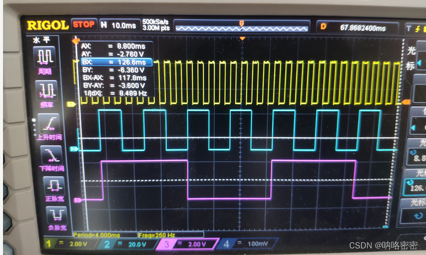
黄色为主定时器14,以250Hz持续输出,蓝色为定时器14的从定时器2,紫色为主定时器2的从定时器0.
TIMER14只是普通的PWM输出,不赘述,只是在初始化时要设置为主从模式,另外要设置触发器使用TIMER14的更新事件,这样TIMER2才可以在TIMER14的每四次更新事件触发输出,TIMER对TIMER0同理。
其次,作为从定时器,是以主定时器作为参考,所以在设置预分频值和周期时要参考主定时器的时钟。
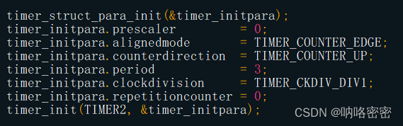
以上图为例,这里预分频值为0,即不对时钟进行分频,并将周期设为3(4-1),这样每四个TIMER14的更新事件便可触发一次TIMER的输出。如果从定时器想改变频率和占空比,修改对应参数即可。这里只是以最简单的方式展示基础的定时器级联。但是需要注意的是定时器的内部级联是有限制的,并不是任意两个定时器都可实现级联,需要参考手册来确定。
定时器的功能太多太多,仅凭一篇帖子肯定说不完,这里仅调出两个进行描述,下面挑出实例进行案例讲解:
恰好有兄弟求助,这里正好借这个问题进行一次实际操作:
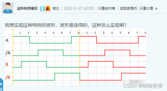
这是一个典型的边沿不对齐的4路波形输出,每个单独的波形都可使用定时器的PWM模式或者比较输出模式来实现,但是同时输出就比较麻烦。此时可以考虑使用定时器的多路比较+DMA来实现。
对于比较输出切换模式,简单的理解就是将比较的值和当前计数器的值进行比较,根据比较结果来输出电平的高低,当比较的值和当前计数的值相等,做出电平的切换。
例如发生匹配之前是高电平,我们设置比较值为500,当定时器计数到500时,匹配成功,将输出改为低电平,反之亦然。
回到案例:
我们从这张图的0点开始计算,一格代表100个计数点,每8个点为一个周期,那么我们定时器的周期就设置为800,计数到800后重0开始再次计数。
那么对于A路,刚开始是高电平,计数到200变成低电平,再计数到700为高电平,然后继续计数到800。完成一个周期。那我们就设置该通道的比较事件触发DMA,初始计数值为200,记到200后触发匹配和DMA,将电平拉低,DMA将计数值改为700。循环下去即可。
那么同理对于/A而言,当CCR=300和 CCR=600时发生输出切换。同样开启该通道的比较事件触发DMA传输,实现CCR寄存器的数据循环更新。
对于B路,原理同上,当CCR=100和 CCR=400时发生输出切换。
对于/B,也可采用相同的方式,但是这里为了展示更多的用法,/B可以不采用DMA,因该波形的起始点刚反生电平翻转,这里可以采用PWM1的输出模式,将CCR设置为500。
基于上述分析,我们用代码实现效果:
首先通过宏定义设置TIMER0的通道外设地址(查手册,上文有介绍):
#define TIMER0_CH0CV                    ((uint32_t)0x40012C34)
#define TIMER0_CH1CV                    ((uint32_t)0x40012C38)
#define TIMER0_CH2CV                    ((uint32_t)0x40012C3C)
定义DMA发送的数组
uint16_t buffer[2] = {200,700};
uint16_t buffer1[2] = {600,300};
uint16_t buffer2[2] = {400,100};
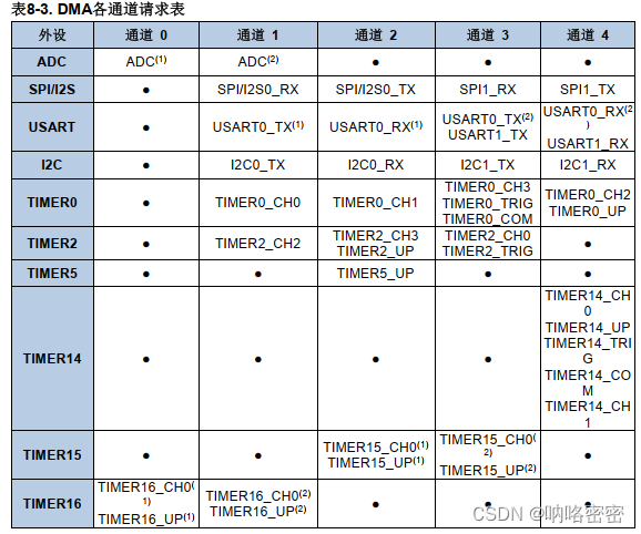
DMA初始化(DMA通道对应定时器通道可参考下表):
/************************************************
函数名称 : timer_dma_config
功    能 : 初始化DMA
参    数 : 无
返 回 值 : 无
作    者 : 呐咯密密
*************************************************/
void timer_dma_config(void)
{dma_parameter_struct dma_init_struct;rcu_periph_clock_enable(RCU_DMA);dma_deinit(DMA_CH1);dma_init_struct.periph_addr  = (uint32_t)TIMER0_CH0CV;//外设地址dma_init_struct.periph_inc   = DMA_PERIPH_INCREASE_DISABLE;dma_init_struct.memory_addr  = (uint32_t)buffer;//内存地址dma_init_struct.memory_inc   = DMA_MEMORY_INCREASE_ENABLE;dma_init_struct.periph_width = DMA_PERIPHERAL_WIDTH_16BIT;dma_init_struct.memory_width = DMA_MEMORY_WIDTH_16BIT;dma_init_struct.direction    = DMA_MEMORY_TO_PERIPHERAL;dma_init_struct.number       = 2;dma_init_struct.priority     = DMA_PRIORITY_ULTRA_HIGH;dma_init( DMA_CH1, &dma_init_struct);dma_circulation_enable(DMA_CH1);dma_channel_enable(DMA_CH1);dma_deinit(DMA_CH2);dma_init_struct.periph_addr  = (uint32_t)TIMER0_CH1CV;dma_init_struct.periph_inc   = DMA_PERIPH_INCREASE_DISABLE;dma_init_struct.memory_addr  = (uint32_t)buffer1;dma_init_struct.memory_inc   = DMA_MEMORY_INCREASE_ENABLE;dma_init_struct.periph_width = DMA_PERIPHERAL_WIDTH_16BIT;dma_init_struct.memory_width = DMA_MEMORY_WIDTH_16BIT;dma_init_struct.direction    = DMA_MEMORY_TO_PERIPHERAL;dma_init_struct.number       = 2;dma_init_struct.priority     = DMA_PRIORITY_ULTRA_HIGH;dma_init( DMA_CH2, &dma_init_struct);dma_circulation_enable(DMA_CH2);dma_channel_enable(DMA_CH2);dma_deinit(DMA_CH4);dma_init_struct.periph_addr  = (uint32_t)TIMER0_CH2CV;dma_init_struct.periph_inc   = DMA_PERIPH_INCREASE_DISABLE;dma_init_struct.memory_addr  = (uint32_t)buffer2;dma_init_struct.memory_inc   = DMA_MEMORY_INCREASE_ENABLE;dma_init_struct.periph_width = DMA_PERIPHERAL_WIDTH_16BIT;dma_init_struct.memory_width = DMA_MEMORY_WIDTH_16BIT;dma_init_struct.direction    = DMA_MEMORY_TO_PERIPHERAL;dma_init_struct.number       = 2;dma_init_struct.priority     = DMA_PRIORITY_ULTRA_HIGH;dma_init( DMA_CH4, &dma_init_struct);dma_circulation_enable(DMA_CH4);dma_channel_enable(DMA_CH4);
}
初始化定时器0,开启通道和DMA:
/************************************************
函数名称 : timer_config
功    能 : 初始化TIMER0
参    数 : 无
返 回 值 : 无
作    者 : 呐咯密密
*************************************************/
void timer_config(void)
{rcu_periph_clock_enable(RCU_GPIOA);/*configure PA8(TIMER0 CH0) as alternate function*/gpio_mode_set(GPIOA, GPIO_MODE_AF, GPIO_PUPD_NONE, GPIO_PIN_8);gpio_output_options_set(GPIOA, GPIO_OTYPE_PP, GPIO_OSPEED_50MHZ,GPIO_PIN_8);gpio_af_set(GPIOA, GPIO_AF_2, GPIO_PIN_8);/*configure PA9(TIMER0 CH1) as alternate function*/gpio_mode_set(GPIOA, GPIO_MODE_AF, GPIO_PUPD_NONE, GPIO_PIN_9);gpio_output_options_set(GPIOA, GPIO_OTYPE_PP, GPIO_OSPEED_50MHZ,GPIO_PIN_9);gpio_af_set(GPIOA, GPIO_AF_2, GPIO_PIN_9);/*configure PA10(TIMER0 CH2) as alternate function*/gpio_mode_set(GPIOA, GPIO_MODE_AF, GPIO_PUPD_NONE, GPIO_PIN_10);gpio_output_options_set(GPIOA, GPIO_OTYPE_PP, GPIO_OSPEED_50MHZ,GPIO_PIN_10);gpio_af_set(GPIOA, GPIO_AF_2, GPIO_PIN_10);/*configure PA11(TIMER0 CH3) as alternate function*/gpio_mode_set(GPIOA, GPIO_MODE_AF, GPIO_PUPD_NONE, GPIO_PIN_11);gpio_output_options_set(GPIOA, GPIO_OTYPE_PP, GPIO_OSPEED_50MHZ,GPIO_PIN_11);gpio_af_set(GPIOA, GPIO_AF_2, GPIO_PIN_11);
/**********************************************************************************/        /* 结构体 */timer_oc_parameter_struct timer_ocinitpara;timer_parameter_struct timer_initpara;rcu_periph_clock_enable(RCU_TIMER0);timer_deinit(TIMER0);timer_struct_para_init(&timer_initpara);timer_initpara.prescaler         = 71;timer_initpara.alignedmode       = TIMER_COUNTER_EDGE;timer_initpara.counterdirection  = TIMER_COUNTER_UP;timer_initpara.period            = 799;timer_initpara.clockdivision     = TIMER_CKDIV_DIV1;timer_initpara.repetitioncounter = 1;timer_init(TIMER0, &timer_initpara);timer_channel_output_struct_para_init(&timer_ocinitpara);timer_ocinitpara.outputstate  = TIMER_CCX_ENABLE;timer_ocinitpara.outputnstate = TIMER_CCXN_DISABLE;timer_ocinitpara.ocpolarity   = TIMER_OC_POLARITY_HIGH;timer_ocinitpara.ocnpolarity  = TIMER_OCN_POLARITY_HIGH;timer_ocinitpara.ocidlestate  = TIMER_OC_IDLE_STATE_HIGH;timer_ocinitpara.ocnidlestate = TIMER_OCN_IDLE_STATE_LOW;timer_channel_output_config(TIMER0, TIMER_CH_0, &timer_ocinitpara);timer_channel_output_config(TIMER0, TIMER_CH_1, &timer_ocinitpara);timer_channel_output_config(TIMER0, TIMER_CH_2, &timer_ocinitpara);timer_channel_output_config(TIMER0, TIMER_CH_3, &timer_ocinitpara);/* 通道0 */timer_channel_output_pulse_value_config(TIMER0, TIMER_CH_0, buffer[0]);/* 设置为匹配时翻转 */timer_channel_output_mode_config(TIMER0, TIMER_CH_0, TIMER_OC_MODE_TOGGLE);timer_channel_output_shadow_config(TIMER0, TIMER_CH_0, TIMER_OC_SHADOW_DISABLE);/* 通道1 */timer_channel_output_pulse_value_config(TIMER0, TIMER_CH_1, buffer1[0]);/* 设置为匹配时翻转 */timer_channel_output_mode_config(TIMER0, TIMER_CH_1, TIMER_OC_MODE_TOGGLE);timer_channel_output_shadow_config(TIMER0, TIMER_CH_1, TIMER_OC_SHADOW_DISABLE);/* 通道2 */timer_channel_output_pulse_value_config(TIMER0, TIMER_CH_2, buffer2[0]);/* 设置为匹配时翻转 */timer_channel_output_mode_config(TIMER0, TIMER_CH_2, TIMER_OC_MODE_TOGGLE);timer_channel_output_shadow_config(TIMER0, TIMER_CH_2, TIMER_OC_SHADOW_DISABLE);/* 通道3 */timer_channel_output_pulse_value_config(TIMER0, TIMER_CH_3, 500);/* 设置为PWM1输出 */timer_channel_output_mode_config(TIMER0, TIMER_CH_3, TIMER_OC_MODE_PWM1);timer_channel_output_shadow_config(TIMER0, TIMER_CH_3, TIMER_OC_SHADOW_DISABLE);/* TIMER0主输出使能 */timer_primary_output_config(TIMER0, ENABLE);/* TIMER0更新DMA请求启用 */timer_dma_enable(TIMER0, TIMER_DMA_CH0D);timer_dma_enable(TIMER0, TIMER_DMA_CH1D);timer_dma_enable(TIMER0, TIMER_DMA_CH2D);
//    timer_dma_enable(TIMER0, TIMER_DMA_CH3D);        /* 使能自动重装载 */timer_auto_reload_shadow_enable(TIMER0);timer_enable(TIMER0);
}
试验效果:
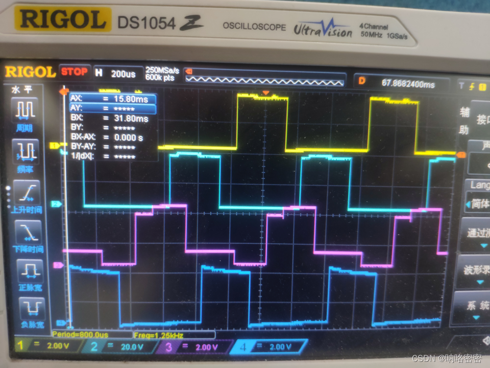
这里波形有点瑕疵,是因为我没有裸板,在之前的板子上测试的,PA8,PA9,PA10外接了RS485电路,该板子还在使用,电路不好破坏,不过不影响试验结果。可以看出来是符合我们的需求的。
此次试验未使用到定时器的级联,解决问题的关键在于对问题本质的分析,对定时器各个功能的熟练掌握,介于时间和篇幅关系,这里就不介绍定时器的所有功能。如有问题,可发帖或跟帖提问,看到会尽量处理,如不好处理我会酌情继续发帖解决。